Lens Type | 5 Elements Advanced Petzval Design |
Focal Length | 518 mm |
Diameter | 108 mm |
Focal Ratio | f/4.8 |
Image Circle | 60 mm |
Focuser | WIFD R&P Focuser |
Focuser Travel Length | 0-30 mm (Ruler to 31mm) |
Adapter Included | Sensor Tilt Xterminator Rotator M79 → M68 Adapter M79 → M54 Adapter M79 → M48 Adapter |
Optional Flattener | No Flattener Required |
Camera Format | Medium Format Full Frame APS-C M4/3 |
Total Weight | 9.58 kg / 21.12 lbs |
OTA Weight | 7.96 kg / 17.55 lbs |
Tube Length | 512.9 mm - 617.9 mm |
Diagram Reports
Spot Diagram


Longitudinal Aberration

MTF Chart

Relative Illumination

Size Diagram


Parts


- Front Bahtinov Mask Cover
- Lens Cover with Bahtinov Mask
- Dew Shield, retractable – 105 mm
- Dew Shield Locking Screw
- WIFD Focuser [ Tension Adjustment Guide ]
- Focus ruler scale window
- Two Speed 1:10 Ratio Fine Knob
- Fine Knob Protecting Cover
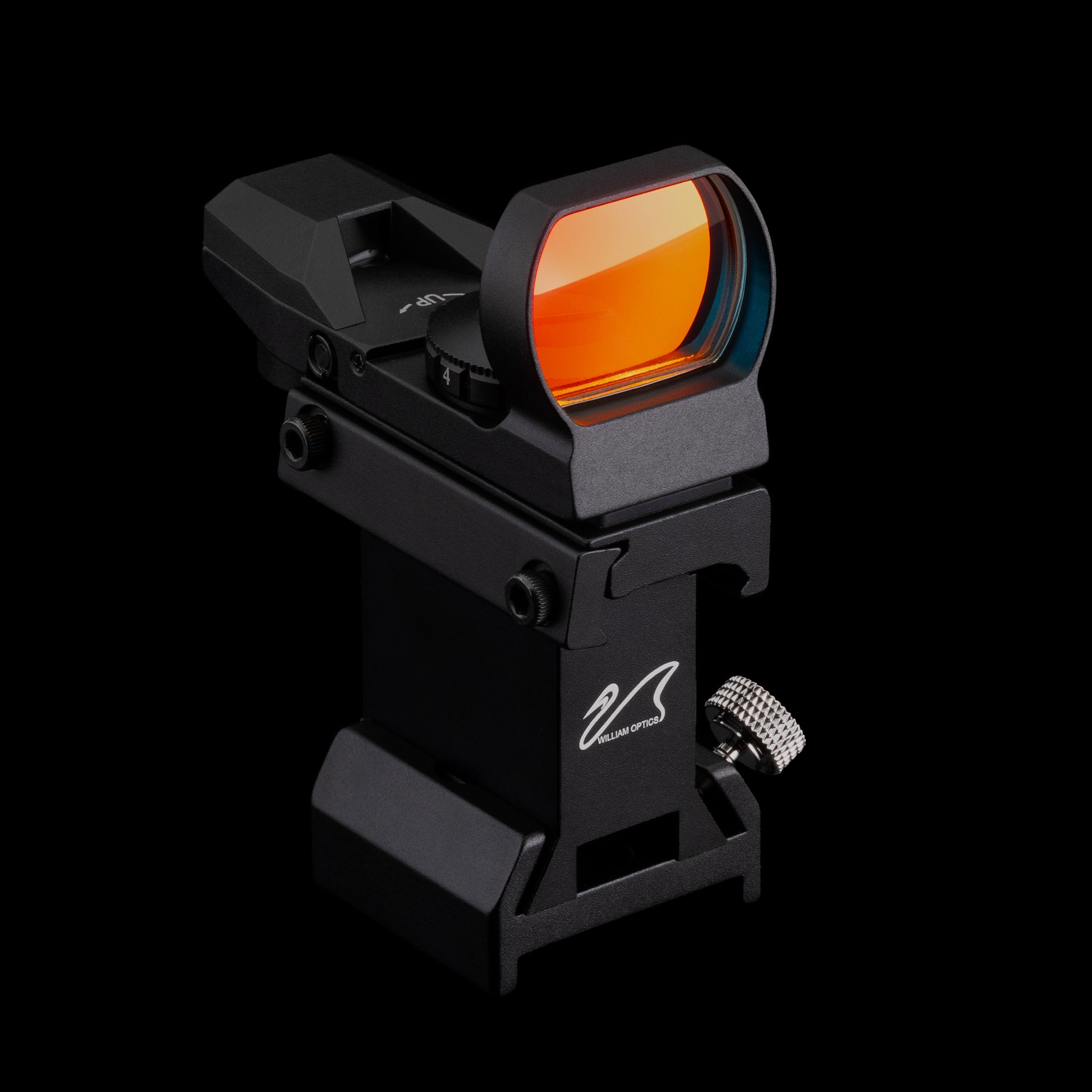
- M4 Screw Holes for Finder Bracket
- Focuser Knob with Temperature Gauge ( Can be removed to attach EAF ) [ Installation Guide ]
- Sensor Tilt Xterminator (STX) with integrated Camera Rotator (CAA) [ Adjustment Guide ]
- STX Adjustment Knob
- CAA Locking Knob (M8*1.0) ( Can be replaced with the H4 set screw when using an off-axis guide system )
- CAA 360° engraved scale
- M79 → M48 Adapter ( M79 → M54, M68 Adapter interchangeable ) [ Replacement Guide ]
- H1.5 Set screws to secure the adapter to CAA
- M48 ( M54, M68 ) Rear Dust Cap
Hardware Parts
Code Name | Image | Quantity | Usage |
 | 2 | Secure the guider to the handlebar | |
 | 1 | Secure the dew shield | |
 | 6 | Spare screws for mounting | |
 | 1 | Replacement for CAA locking knob (in case of interference with accessories) |
Operation Guide
Camera Adapter Replacement


- Tighten the CAA Locking Knob securely.

- Loosen the three set screws on the adapter with a 1.5 mm hex key.

- Rotate the adapter counterclockwise to remove it

- Install the replacement adapter by reversing the above procedure.
Note
Three set screws are integrated into the adapter to control its connection to the CAA rotation mechanism.
- Tightening the screws allows the adapter and CAA to rotate as a single assembly
- Loosening them enables independent removal of the adapter.
Sensor Tilt Adjustment (STX)
- Locate the pair of diagonally opposing screws corresponding to the affected corners.
- Use 2mm hex key to release (turn clockwise) the STX knob near the corner where the sensor is too far.
- Push out (turn counterclockwise) the opposite knob accordingly.
- Do not touch the Auto Tension Screws. It may disrupt balance or cause loosening.
- Make small adjustments — turn each knobs only about 1/8 turn at a time, and avoid rotating any knob beyond a full 360°.
- Use gentle pressure when turning — overtightening may affect collimation or introduce unwanted stress.


Any 2mm rod or hex key can be used to twist the knob mechanism.


- After each adjustment, perform a test exposure to check the star shape and alignment. Fine-tune as needed until the stars are round and sharp across the entire frame.
Tips & Notice
- Perform adjustments in a stable environment — wait for your optics and sensor to cool, and avoid large temperature fluctuations during testing.
- Typical tilt tuning takes 2–4 test exposures. Final adjustment needs may vary depending on your camera, filters, and backfocus configuration.
- Tilt does not require frequent adjustment. Once properly set, it should remain stable unless major components (e.g., camera, tilt plate, or spacing) are changed.
- Lock the CAA knob before adjusting tilt to ensure consistent and accurate results.
- Do not overload the STX adjusters — keep constant load under 4 kg and impact load under 2 kg to preserve mechanical precision.
Focuser Tension Adjustment
William Optics focusers are typically smooth and ready to use without any adjustment. For larger telescopes, tightening the Quick Tension Adjustment Knob can help prevent tube slippage. Other than this, we recommend not touching any screws on the focuser. If adjustment is necessary, please consult a qualified technician.
There’s two side to build WIFD focuser tension:
BOTTOM / Rack & Pinion Gear


- Quick tension adjustment knob
- Smoothness adjustment - Pull in (3mm Hex)
- Smoothness adjustment - Push out (2mm Hex)
- Please Don’t Touch
- Top cover screw Can be removed to attach the electronic devices such as EAF (refer to Installing EAF) or be used as a spare.
Telescope models from June 2025 no longer include the top cover screw.
TOP / Focuser Draw Tube


- Focuser Draw Tube Tension Screws Please Don’t Touch
- Guider/Finder bracket mounting screws (2.5mm Hex)
Notice
- When operating the telescope with a motorized focuser, do not overtighten the focuser tension. Excessive tension may damage the focuser mechanism.
- Make small and slow adjustments. Do not turn anything too much at once.
Back Spacing Range on Petzval Systems
Petzval telescopes do not rely on a single, exact back focus distance. Instead, they are designed to reach focus within a supported back spacing range, providing flexibility when using different cameras and accessories.
As long as the complete camera setup falls within this range, the focuser can reach focus normally. If the setup goes beyond it, focus may no longer be achievable.

For astrophotography, a back spacing of 55 ± 3 mm is recommended to limit drawtube extension and reduce the risk of light leakage.
For more details on back spacing, see the support article Back Spacing Range on Petzval Systems
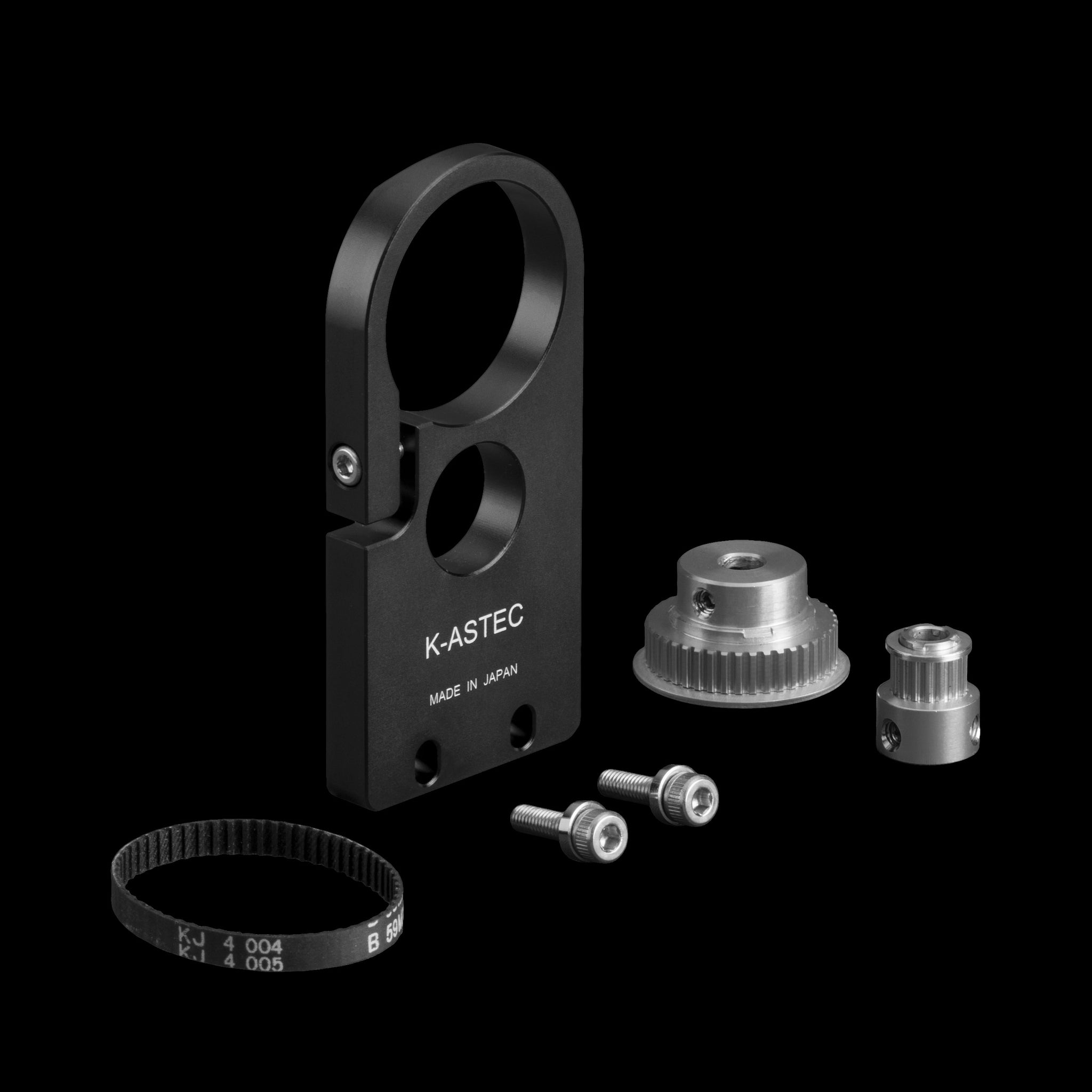
Installing EAF


- Turn the telescope over and remove the Tension screw.


- Remove the top cover screw near the temperature gauge with 2mm Allen key.
Starting from June 2025, new telescope models no longer include the top cover screw. (Skip Step 2)

- Release (don’t remove) two inner knob screws.

- Remove the temperature gauge knob.

- Find the flat side on the shaft and turn it to face the hole.


- Put the 5-6mm Flexible coupling on the shaft and lock the two inner screws.


- Put the EAF body on and lock the two inner screws.
On Step 6 & 7:
Please make sure one of the screws is lock on the flat side (D-cut profile)


- Align the screw holes.

- Lock the four M4 bracket screws.

Installing Off-axis Guide System

When installing an off-axis guiding system, the CAA Locking Knob may interfere when rotating the camera. In this case, you can replace it with the included H4 set screw to avoid the conflict.


Care & Safety Instructions
Solar Safety Warning
Never point your telescope or finder scope at the Sun without a proper solar filter securely mounted to the front of the telescope.
Even a brief, unfiltered glimpse of the Sun can permanently damage your eyes or your camera’s image sensor.
- Use only front-mounted solar filters made by trusted manufacturers. These filters must cover the front of the telescope’s dew shield securely.
- Do not use solar eyepiece filters. They are unsafe and can fail under sunlight.


With the correct solar filter in place, you can safely observe and photograph the Sun without damaging your eyes, your camera, or your telescope.
Telescope Care & Storage
To preserve the optical quality and lifespan of your William Optics telescope, please follow these essential care and storage practices:
- Allow time to acclimate After use, let the telescope adjust to room temperature before storage. During this period, keep the optical tube open and uncovered to allow moisture to evaporate naturally.
- Ensure dryness Make sure the entire telescope is completely dry, especially the optics and interior tube, and free of dew or moisture before putting it away.
- Use proper storage conditions Store your telescope in a dry, dust-free environment with a stable temperature. Avoid high heat or humidity. Dehumidifiers or silica gel are recommended for long-term protection.
- Prevent dust accumulation Always place dust caps on both ends when not in use, or cover the telescope with a clean plastic sheet if it’s not stored in a case.
Following these steps will help maintain optimal performance and prevent damage to sensitive components such as lenses, mirrors, and coatings.
For a detailed cleaning and maintenance guide, please refer to the full article: Cleaning and Maintenance of Telescopes
Clearance Around WIFD Focuser
To avoid interference between the focuser knobs and the mount, make sure the telescope is properly aligned on the mounting rings.
Loosen the rings slightly and adjust the telescope position so that both focuser knobs are level and parallel to the mount. This ensures sufficient clearance from the saddle plate and prevents accidental contact or obstruction during use.